API PIPING PLANS
API Piping Plans are American Petroleum Institute standard configuration of piping accessories, instruments & fluids design which controls the environment around the seal, so these are widely used in the industry.

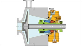











PLAN 02
Dead Ended Seal Chamber with no flush fluid circulation. Used in cool clean fluids with high specific heat, low seal chamber pressure, in relatively low speed pumps.
PLAN 03
Circulation created by the design of the Seal Chamber. The seal chamber has a tapered bore and no throat bushing. Taper Bored Seal Chamber shape creates a velocity profile that expels solids & circulates cool fluid to the Seal.
PLAN 11
Re-circulation from a high-pressure region of the pump (typically pump discharge piping) through a flow control orifice to the seal. This is the default seal flush plan for all Arrangement 1 and 2 seals.
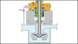
PLAN 13
Re-circulation from the seal chamber through a flow control orifice and back to the pump suction or pump suction piping. It is the standard flush plan selection for vertical pumps that are not provided with a bleed bushing below the seal chamber.
PLAN 14
Re-circulation from pump discharge through a flow control orifice to the seal and simultaneously from the seal chamber through a flow control orifice to pump suction. This allows fluid to enter the seal chamber and provide cooling while continuously venting the pressure in the seal chamber.
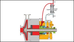
PLAN 21
Re-circulation from a high-pressure region of the pump (typically pump discharge piping) through a flow control orifice and cooler, then into the seal chamber. Provides a cool flush to the seal. This may be needed to improve the margin to vapor formation, to meet secondary sealing element temperature limits.
PLAN 23
Re-circulation from a circulation device in the seal chamber through a cooler and back into the seal chamber. The seal is equipped with an internal circulating device that circulates seal chamber fluid through a cooler and back to the seal chamber.
PLAN 31
Re-circulation from a high-pressure region of the pump (typically the pump discharge piping) through a cyclone separator delivering the clean fluid to the seal chamber. The solids are delivered to the pump suction line. This is used for water service to remove sand or pipe slag.
PLAN 32
Flushing product is brought from an external source to the seal. The external flush should be continuous and reliable even during nonstandard situations. Used in services containing solids or contaminants, in which a suitable cleaner or cooler external flush will improve the seal environment.
PLAN 41
Re-circulation from a high-pressure region of the pump (typically the pump discharge piping) through a cyclone separator delivering the clean fluid to a cooler and then to the seal chamber. The solids are delivered to the pump suction line. combination of Piping Plan 21 and Piping Plan 31 and is specified only for hot services containing solids.
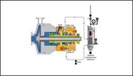
PLAN 52
External reservoir providing buffer liquid for the outer seal of an Arrangement 2 seal. The buffer liquid shall be maintained at a pressure less than seal chamber pressure and less than 0.28 MPa (2.8 bar) (40 psi). Buffer liquid is circulated to and from the reservoir by means of an internal circulating device.
PLAN 53A
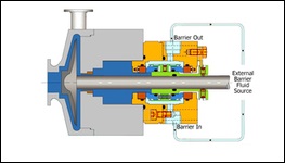
Pressurized external barrier fluid reservoir supplying clean fluid to the seal chamber. The reservoir pressure should always exceed the maximum seal chamber pressure by a minimum of 0.14 MPa (1.4 bar) (20 psi). Barrier liquid is circulated to and from the reservoir by means of an internal circulating device. Used with Arrangement 3 seal and services where no leakage to atmosphere can be tolerated.
PLAN 53B
External barrier fluid system pressurized by a bladder accumulator supplying clean liquid to the seal chamber. The accumulator and barrier liquid are maintained at a pressure greater than seal chamber pressure. Barrier liquid is circulated through the system by means of an internal circulating device.
PLAN 53C
External barrier fluid system pressurized by a piston accumulator supplying clean liquid to the seal chamber. The barrier liquid is maintained at a pressure greater than seal chamber pressure. Barrier liquid is circulated through the system by means of an internal circulating device.
PLAN 54
Pressurized external barrier fluid system supplying clean liquid to the barrier fluid seal chamber. Piping Plan 54 is used with Arrangement 3 liquid seals and the barrier liquid is maintained at a pressure greater than seal chamber pressure. Barrier liquid is circulated by an external pump or pressure system.
PLAN 62
Quench stream is brought from an external source to the atmospheric side of the seal faces. It is used in selected single seal applications to exclude the presence of oxygen to prevent coke formation (hot hydrocarbon services) and to flush away undesirable material buildup around the dynamic seal components (caustic and salt services).
PLAN 65A
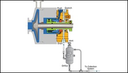
Atmospheric leakage collection and detection system for condensing leakage. Failure of the seal will be detected by an excessive flow rate into the leakage collection system. This plan is used when pumped fluid condenses at ambient temperatures. Seal leakage detection piping plan normally used with Arrangement 1 seals where leakage is expected to be mostly liquid (not gas).
PLAN 65B
Atmospheric leakage collection and detection system for condensing leakage. Failure of the seal will be detected by a cumulative leakage into the system. This plan is used when pumped fluid condenses at ambient temperatures. Seal leakage detection piping plan normally used with Arrangement 1 seals where leakage is expected to be mostly liquid (not gas).
PLAN 66A
Throttle bushings in the seal gland minimize the seal leakage leaving the seal gland and allow for detection of a seal failure. Use in Arrangement 1 applications where it is required to limit leakage in case of a seal failure or it is required to monitor excessive leakage.
PLAN 66B
Orifice plug in the drain port minimizes the seal leakage leaving the seal gland and allows for detection of a seal failure. use in Arrangement 1 applications where it is required to limit leakage in case of a seal failure or it is required to monitor excessive leakage.
PLAN 72
Externally supplied buffer gas for Arrangement 2 seals. Buffer gas is maintained at a pressure less than seal chamber pressure. In normal operation, the buffer gas pressure should not exceed 0.07 MPa (0.7 bar) (10 psi). used on Arrangement 2 un-pressurized dual seals that use a dry-running containment seal.
PLAN 74
Externally supplied barrier gas for Arrangement 3 seals. Barrier gas is maintained at a pressure greater than seal chamber pressure. used on Arrangement 3, dual pressurized seals, where the barrier medium is a gas. The most common barrier gas is plant nitrogen. The supply pressure to the seal is typically at least 0.17 MPa (1.7 bar) (25 psi) greater than the seal chamber pressure.
PLAN 75
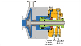
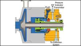
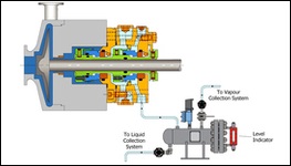
Containment seal chamber leakage collection system for condensing or mixed phase leakage on Arrangement 2 seals. This plan is used when pumped fluid condenses at ambient temperatures.
PLAN 76
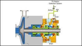
Containment seal chamber drain for non-condensing leakage on Arrangement 2 seals. This plan is used if the pumped fluid does not condense at ambient temperatures. This system is supplied by the vendor. Used on Arrangement 2, un-pressurized dual seals, which also utilize a dry containment seal and where leakage from the inner seal will not condense.


